Structure
Truefin is 100% nonmetallic in order to ensure rust and/or corrosion can never be an issue in fresh or salt water.

Generally, there are four components in the design of Truefin:
1. Fin - (black) injection molded Monprene® (Shore 72A)
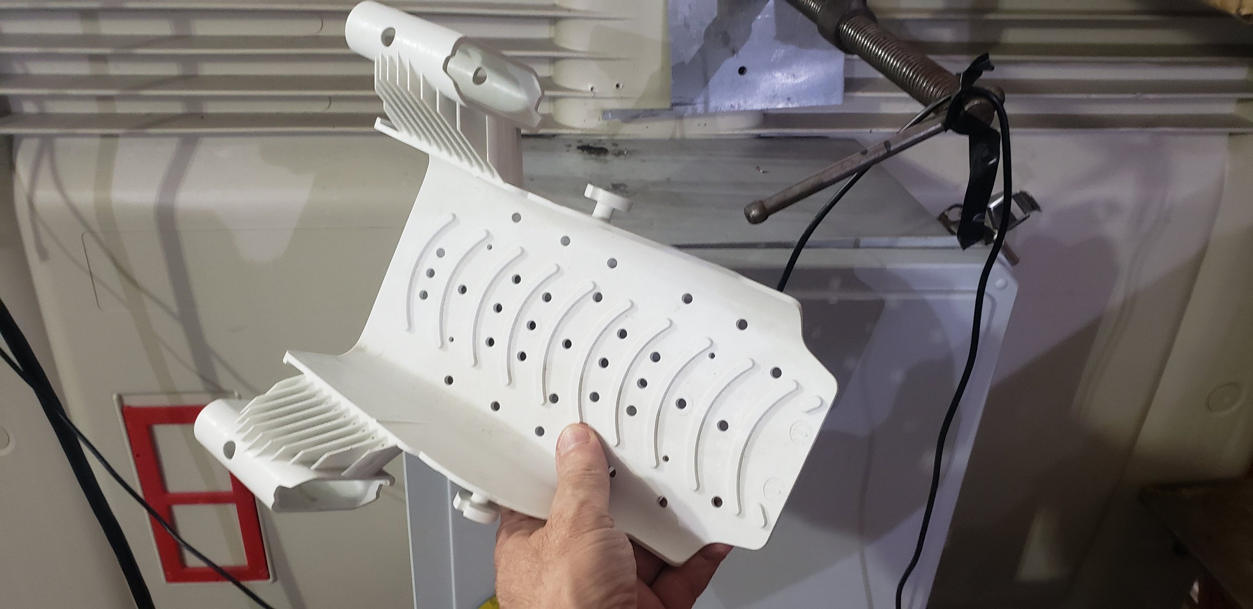
The bottom of the foot pocket is reinforced with an overmolded substrate chassis and is relatively rigid, and is extended to support the user’s heel. Upper surface of foot pocket is not over molded, and is flexible and tapered thin (down to 0.140”) to the center top edge which improves comfort and reduces concentrated forces at the top (instep) of the user's foot. The foot pocket includes toe vent holes in order to minimize parachuting while moving through the water and also to minimize suction and allow drainage while facilitating removal of the fin from the user's foot. The external sole or power plate of the fin includes relatively complex geometry of a low profile non-slip design to both maximize traction while wearing the fin out of water, yet minimize turbulence or drag forces while finning in water.

2. Over molded chassis (substrate)
Injection molded glass filled polypropylene (19,000psi tensile strength). Standard size heel strap posts are part of chassis and are also overmolded.


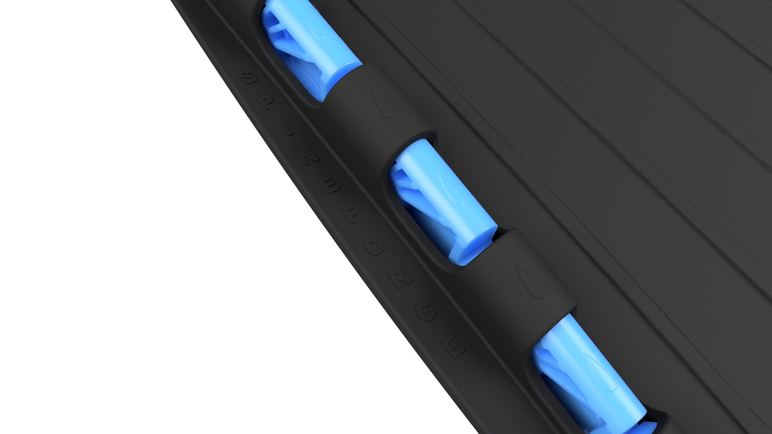
3. Artificial vertebra
Glass filled injection molded nylon (21,000 psi tensile strength, 84 Shore D). Note bone = 90 Shore D.


4. Leaf spring pin (red)
Glass filled polypropylene
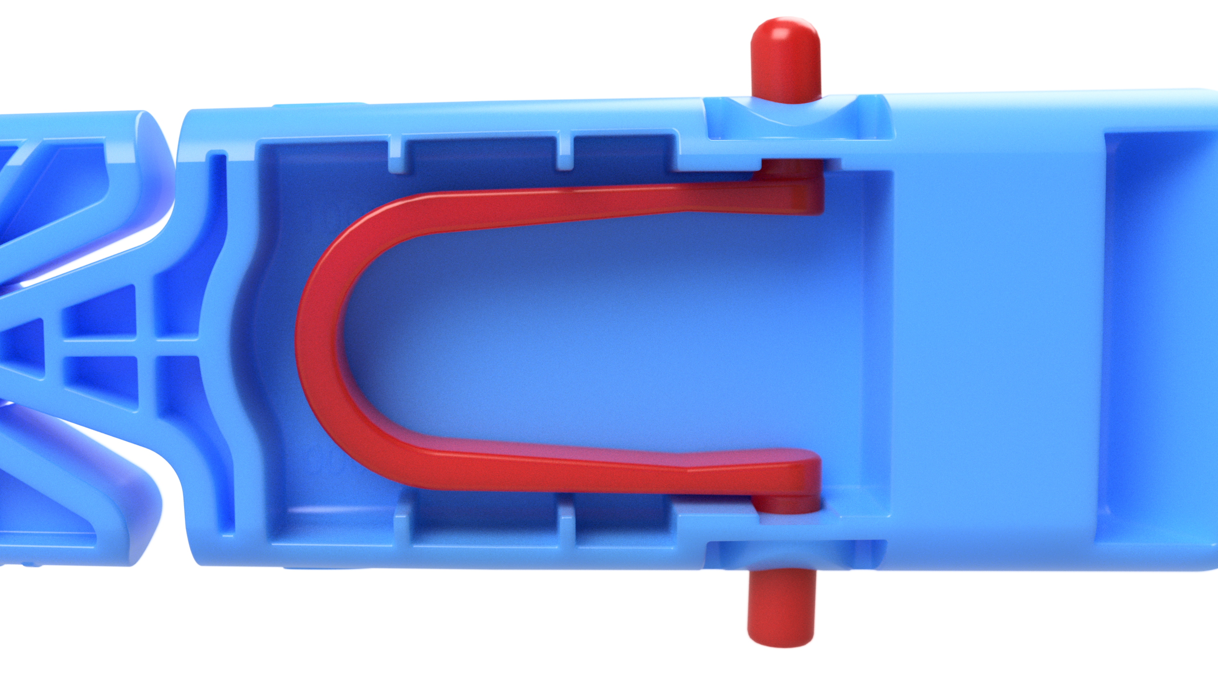
Spring pin secures removable spines

Spines locked into chassis
Spine Geometry
Each fully assembled Blue '412 spine has six blocks or six artificial vertebrae, and there are five 'head and socket' collision angle sites between the blocks. Vertebrae part numbers: 10000, 20412, 30412, 40412, 50412, and 60412 each have collision angles of four degrees (4°) in the 'toe up' direction, and twelve degrees (12°) in the 'toe down' direction, resulting in the assembled spine articulation at each side of the neutral axis of the fin rails to be twenty degrees (20°) in the 'toe up' direction, and sixty degrees (60°) in the 'toe down' direction [note: 5 x 4° = 20°, and 5 x 12° = 60°].
The trailing or terminal vertebra 60412 is relatively long, and this is to create an 'unswept' trailing edge of the blade which is preferred when considering vortex sheet shedding (Kármán vortex shedding. Insert Reference - Lighthill #). Traditional fins, and particularly flexible traditional fins, have 'swept' trailing edges due to the yielding elastomeric properties of the trailing ends of the fin rails, and where small regions of the trailing edge of the blade may flex nearly perpendicularly to the longitudinal direction of the fin resulting in a portion of the water exiting off of the trailing edge of the blade to be directed toward inefficient directions.

During spine installation, the hash marks (III) on the vertebrae are assembled next to the hash marks (III) at the bottom of the fin rail, and the tear drop marks (💧) marks on the vertebrae are assembled next to the tear drop marks (💧) at the top of the fin rail.